The Stepper Motor Finally Moved: A Hardware Debugging Story
There is a specific kind of feeling you get when a physical thing you wired together starts moving for the first time. It’s different from shipping a feature or getting a test to pass. It’s more animal than that.
The stepper motor on the Root Meridian moved today. It took one session and a full cup of coffee. Here’s the whole story.
Where We Left Off
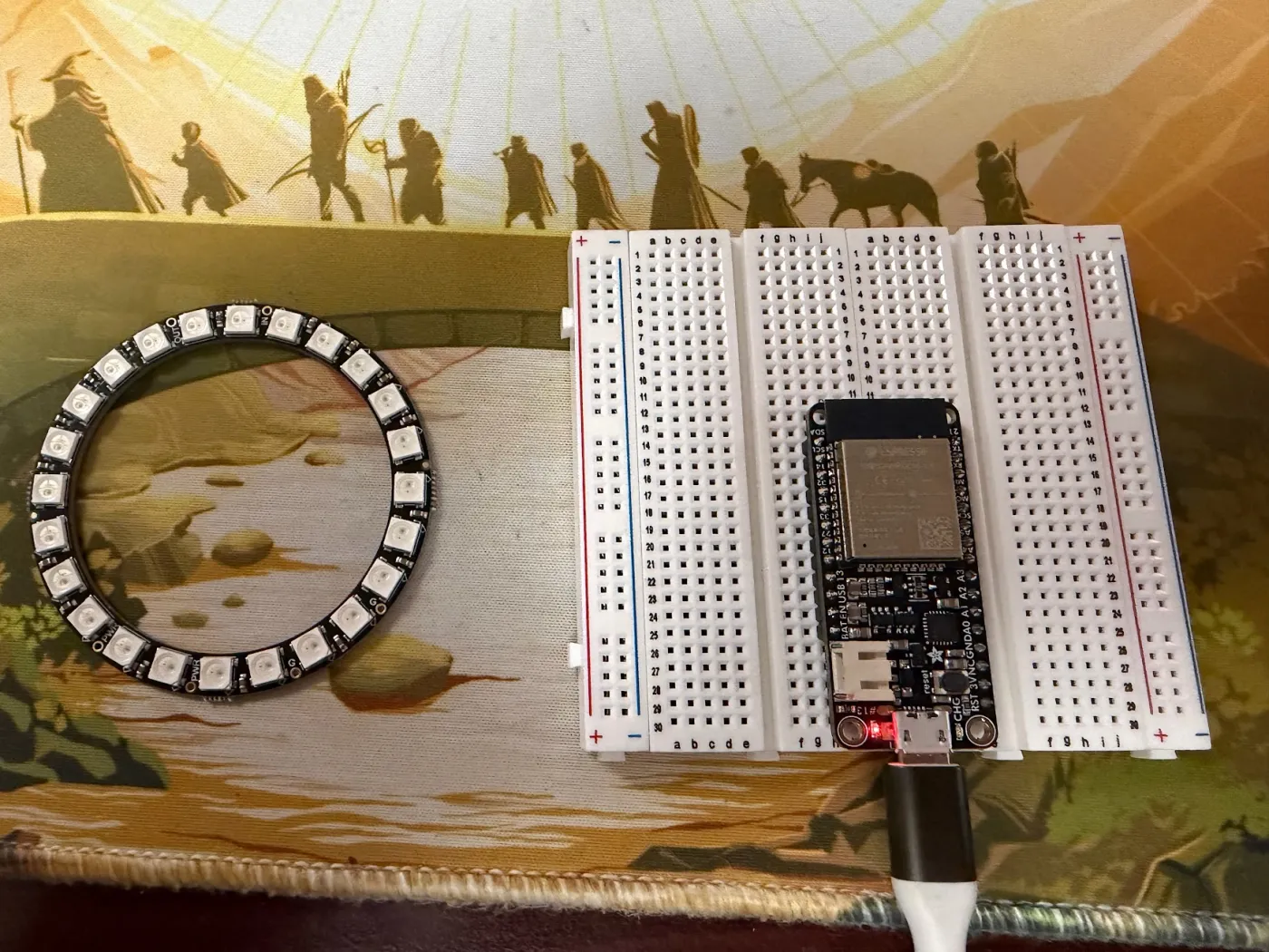
Last post, I had a NeoPixel ring breathing green in a simulator. The real hardware had arrived and was sitting on my desk, but I hadn’t touched it yet. The plan was: simulate first, then wire the real components.
That plan lasted about one session.
The Wokwi simulator — which I’d been using inside Cursor — has a known bug on Windows 11 where the serial terminal stays completely blank. No output, no error, just silence. After half an hour of configuration attempts I gave up and switched to the real ESP32. Sometimes the fastest path forward is the one with actual electrons.
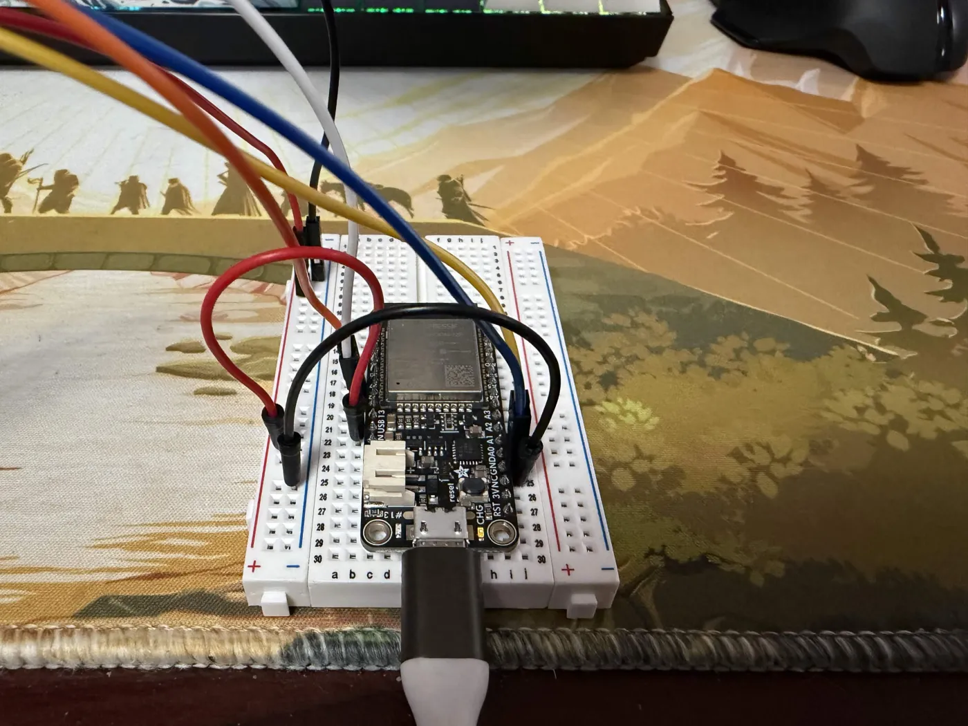
Flashing the Real Board
The Adafruit HUZZAH32 uses a CP2104 USB-to-UART bridge to communicate with your computer. On Windows, this requires a driver that does not come pre-installed. When I plugged in the board, Device Manager showed it under “Other Devices” with a yellow warning triangle — unrecognized hardware.
Fix: download the Silicon Labs CP210x VCP driver. The board immediately showed up as COM3, Arduino IDE could see it, and I flashed the firmware on the first try.
The serial monitor lit up:
=== ROOT MERIDIAN ===
type ? for commands
=====================

[515ms] LEDs ready
[515ms] Motor ready — waiting for commands
That banner alone felt like a victory. The chip boots, runs my code, and talks back. Moving on.
The Motor That Refused To Move
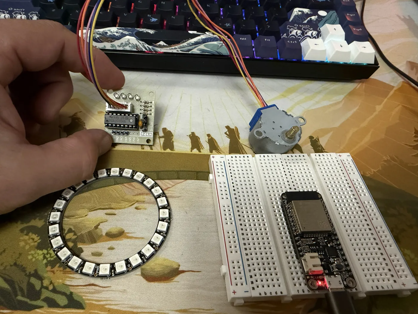
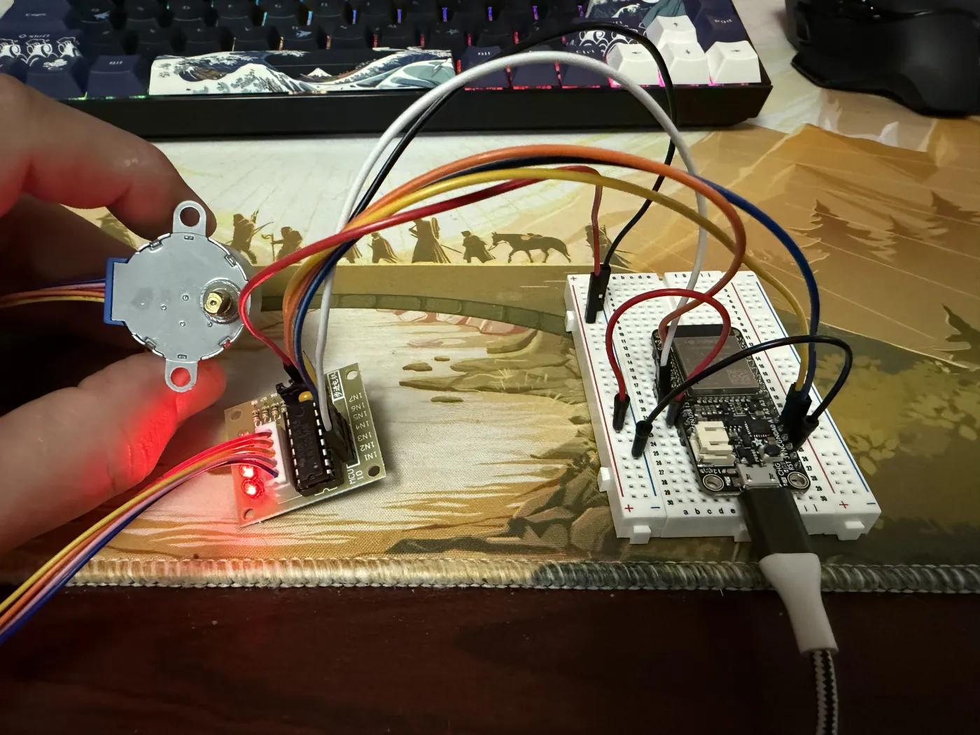
The firmware has a spin command that throws the compass into erratic mode — random rapid movements meant to look like the compass is confused. I wired up the 28BYJ-48 stepper motor and ULN2003 driver board, typed spin into the serial monitor, and:
[5190ms] MOTOR → ERRATIC
>> spin!
The firmware received the command. The code ran. The motor did not move.
This is the specific frustration of hardware debugging: the software is doing its job perfectly. The problem is somewhere in the physical world, which doesn’t have stack traces.
Lesson 1: Look at the board, not just the serial monitor
I had no idea where to start. The serial output confirmed the firmware was running and had received the command — that was it. No error, no indication anything was wrong on the software side. I was staring at code that looked correct, a board that looked wired correctly, and a motor that was just sitting there.
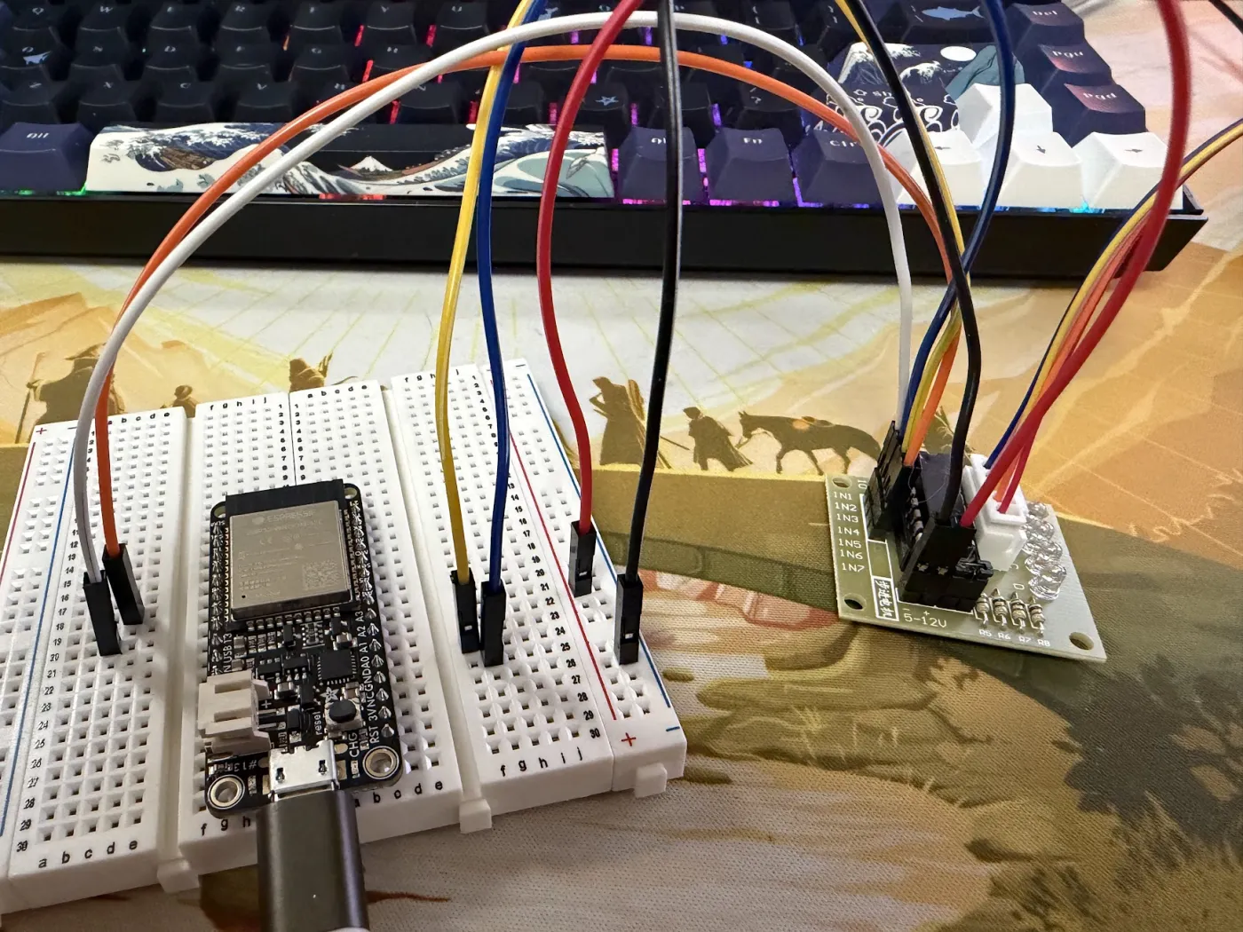
I didn’t know what I was looking for until I actually looked at the ULN2003 board itself. It has four indicator LEDs, one per coil winding, that light up when the firmware is actively driving that phase. All four were completely dark — not flickering, not dim, just off. The firmware was commanding motion and nothing on the driver board was responding at all. That told me the problem wasn’t in the code.
Lesson 2: The breadboard power rails don’t have power unless you give them power
This is obvious in retrospect but genuinely surprising when you’re new to breadboards. The + and - rails along the sides of a breadboard are just conductors. They carry whatever voltage you put into them — nothing else. They are not magic power sources.
I had moved the power wires for the ULN2003 to the breadboard’s + and - rails, thinking “these are the power rails, power should flow.” But nothing was feeding voltage into those rails from the ESP32. The rails were floating at 0V.
Lesson 3: Get a multimeter
I dug out an old Sperry DM-6400. With the black probe on the - rail and the red probe on the + rail, it read exactly 0.00V. Confirmed.
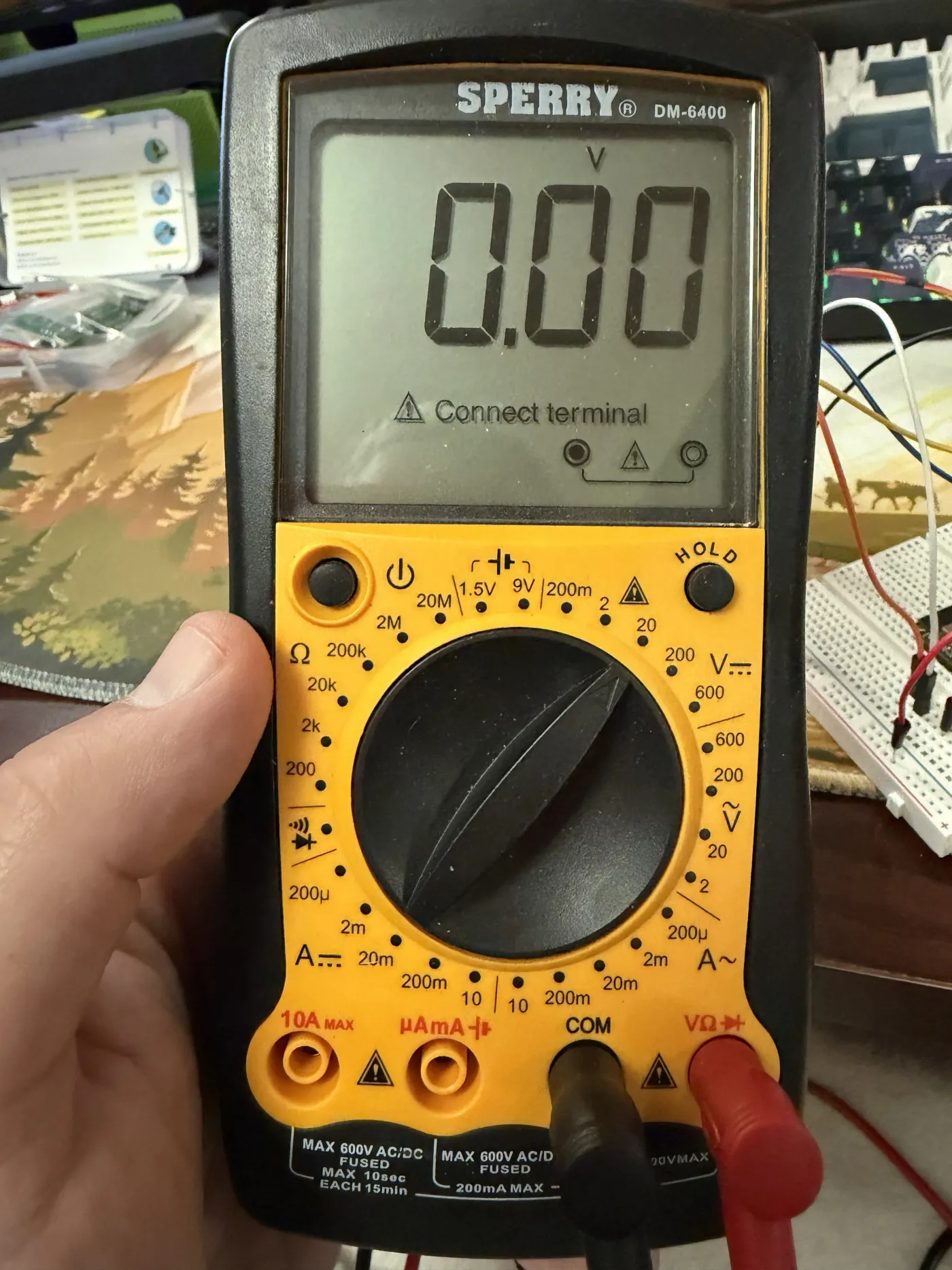
For anyone new to multimeters: set it to DC voltage (the V with a straight line, not the wavy line — that’s AC), put the black probe in COM, red probe in VΩ, and touch the probes to whatever you want to measure. The probe tips don’t fit into breadboard holes — just touch them to the leg of any wire that’s already seated in the hole.
The Fix
The Adafruit HUZZAH32 has a pin labeled USB on the silkscreen — this is VBUS, 5V output when USB is connected. It’s on the right rail of the board, close to the USB connector. I added two wires:
- ESP32 USB/VBUS → breadboard
+rail - ESP32 GND → breadboard
-rail
Then:
- ULN2003 power
+→ breadboard+rail - ULN2003 power
-→ breadboard-rail
The multimeter immediately read 4.97V. The red LED on the ULN2003 lit up.
Lesson 4: Breadboard row numbers are not GPIO pin numbers
While debugging the signal wiring, I discovered I’d been referencing breadboard row numbers instead of the pin labels printed on the ESP32 board itself. Breadboard row 33 has absolutely nothing to do with GPIO33. The GPIO numbers are labeled in tiny silkscreen text on the board edge — those are the ones that matter.
It Moved
All four signal LEDs on the ULN2003 lit up. The motor started turning.
Slowly. Too slowly, I thought — I had no idea yet whether this was all the 28BYJ-48 could do or if I was leaving speed on the table. The 28BYJ-48 is a geared stepper with 2048 steps per revolution; at 800 steps per second, one full rotation takes about 2.5 seconds. Turns out that’s just what these motors do, and for a compass needle it’s actually fine. Slow is relative.
compass east sent the needle smoothly to East. lockon west crawled it there with a satisfying deliberateness. spin made it twitch and stutter like a confused compass.
It worked exactly as designed.
A Known Bottleneck (Not Fixed Yet)
While debugging I noticed the delay(16) in the main loop caps how often AccelStepper.run() gets called — roughly 62 times per second. AccelStepper wants to be called as fast as possible; that delay is a real ceiling on step rate.
The right fix is time-gating the LED updates instead of blocking the whole loop, so motorUpdate() runs every iteration without a delay. I tried it — it’s noticeably snappier — but it broke the seek command in testing, so I reverted it. Something to revisit once the NeoPixel ring is wired in and I can test the full system together.
Developer Quality of Life
One small thing that made iteration faster: a root package.json with scripts for the firmware workflow. Coming from web dev, typing npm run deploy feels a lot more natural than remembering the full arduino-cli invocation.
{
  "scripts": {
    "build": "arduino-cli compile --fqbn esp32:esp32:featheresp32 firmware/compass",
    "flash": "arduino-cli upload --fqbn esp32:esp32:featheresp32 -p COM3 firmware/compass",
    "listen": "arduino-cli monitor -p COM3 --config baudrate=115200",
    "deploy": "npm run build && npm run flash",
    "stub": "node bot/stub/server.js"
  }
}
Requires arduino-cli installed separately from the Arduino IDE, but worth it.
What The Firmware Looks Like Now
The full command set, usable over serial with DEBUG 1 set:
compass [north|east|south|west]   — smooth seek to direction
spin                               — erratic mode (compass confused)
lockon [north|east|south|west]    — slow dramatic crawl to target
gem [player] [available|spent]    — set a gem state
reset                              — all gems available, needle north
All motion modes are working on real hardware. The architecture — motorUpdate() called every loop tick, LED animation driven by a float time value — is holding up cleanly.
What’s Next
The Pinecil V2 soldering iron is arriving this week. Once it’s here:
- Solder the NeoPixel ring — the through-hole pads need proper solder joints, not just wire contacts
- Test gem colors on real hardware — topaz, emerald, ruby, diamond pulsing in their quadrants
- Add WiFi + the HTTP server — so the Discord bot can actually reach the ESP32
- Build the Discord bot —
!compass,!spin,!resetcommands for the DM
The compass is going to the table. It’s just a matter of time.
The Root Meridian is an open build log. All firmware lives in the repo. If you’re building something similar, the most useful advice I can give: get a multimeter before you need one, and read the actual silkscreen labels on your board.