A Cheap Yellow Display That Tells Us What to Wear
The board powered up, played its factory demo, and then refused to exist as far as my computer was concerned. The culprit turned out to be where I plugged it in.
This is the first hardware chapter of Little Butler, a private home tool I’m building: small helpers for the house (workout nudges, chores, and now a desk display) all talking to one server on my own network. There are no cloud backends and no analytics, and the repo is private, so there’s no link this time. The display is an ELEGOO “Cheap Yellow Display”, the ESP32-2432S028R: a 2.8” 240×320 ILI9341 screen with an XPT2046 resistive touch panel and USB-C. I worked on it with Claude Code, and partway through I moved the project from Cursor into VS Code so I could use the PlatformIO extension.
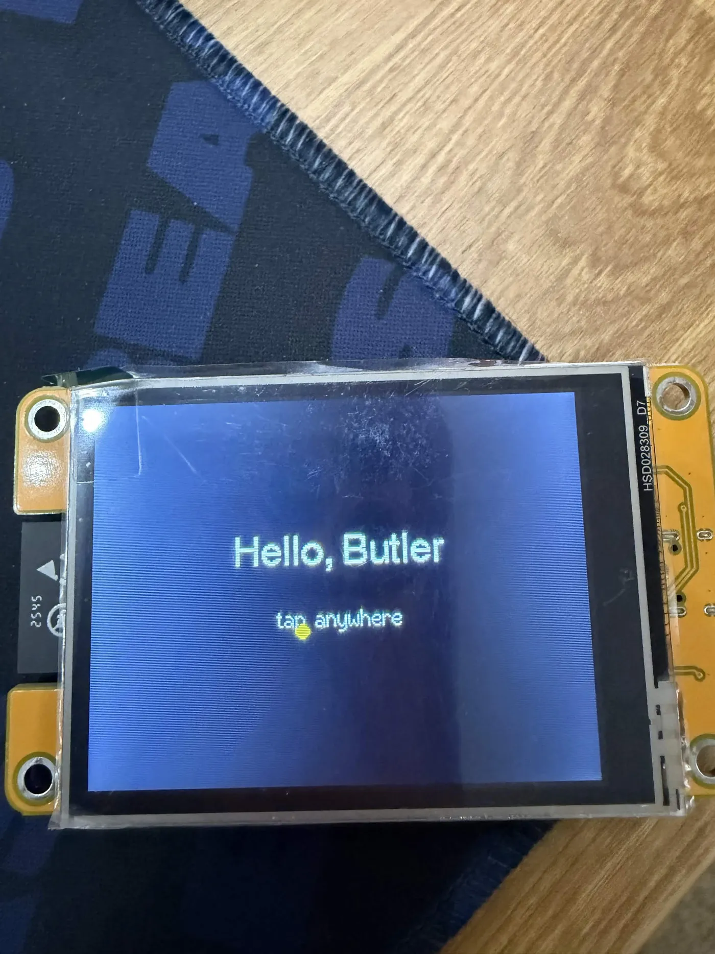
That’s first light: the “Hello, Butler” test screen, with a yellow dot drawn wherever I touch. Getting there took a few detours.
A board that powered up and never showed up
PlatformIO’s Python environment (~/.platformio/penv) didn’t exist until the extension finished its first-run install, so pio wasn’t on my path for a while. After that, the first build got as far as compiling my own code (more on that below). Flashing was the other problem: WSL2 can’t see USB devices on its own.
You need usbipd-win on the Windows side. I first ran usbipd list inside WSL, where it doesn’t exist, and apt helpfully suggested an unrelated package. In an admin PowerShell instead:
winget install --interactive --exact dorssel.usbipd-win
usbipd list
My board never showed up. It was clearly alive once I found a cable that powered it (the first one didn’t even light the screen, and the factory demo came up on the second), but the list only had my input devices, webcam and mic, plus a line that looked promising: Unknown USB Device (Port Reset Failed). That one was a red herring. It stayed after I unplugged the board, and it stayed after a reboot, so it’s some other device entirely. I still don’t know what.
I tried a second cable, then a USB splitter, then a reboot. What finally worked was plugging straight into a port on the motherboard. I changed the cable and the port along the way, so I can’t tell you for sure how much each mattered, but a splitter in the middle was clearly not helping. After that:
1-5 1a86:7523 USB-SERIAL CH340 (COM5)usbipd bind --busid 1-5
usbipd attach --wsl --busid 1-5Back in WSL it showed up as /dev/ttyUSB0. My user also had to be in the dialout group, followed by a wsl --shutdown so the group applied. The attach has to be repeated every time the board is replugged or WSL restarts. I wrote that down in the firmware README.
The touch library that wouldn’t compile
The first real build failed on one line:
src/main.cpp:31:23: error: no matching function for call to 'XPT2046_Touchscreen::begin(SPIClass&)'I had pinned the touch library to a specific commit, and that commit only drives the global SPI object. On the CYD the touch chip sits on its own pins, separate from the screen’s bus. The fix was to remap the global SPI to the touch pins first and let the library’s own begin() be a no-op:
// The pinned XPT2046 library only uses the global SPI (VSPI), so remap its pins first;
// its own SPI.begin() is then a no-op.
SPI.begin(TOUCH_CLK, TOUCH_MISO, TOUCH_MOSI, TOUCH_CS);
touch.begin();
That relies on how arduino-esp32 2.x treats a second begin(), so I’d call it a known workaround, not a guarantee. It works on my board.
Calibrating touch with a stylus
My first touch ranges were guesses, and finger taps in the four corners landed 10 to 19 pixels short of each edge. A finger can’t reach the extreme corners of the panel, so I switched to the stylus tool. Pressed into the very corners, it reported raw X of roughly 200 to 245 at the left edge and 3666 to 3690 at the right, and raw Y of roughly 323 to 396 at the top and 3792 to 3869 at the bottom. The final mapping:
int x = constrain(map(p.x, 220, 3675, 0, tft.width() - 1), 0, tft.width() - 1);
int y = constrain(map(p.y, 360, 3830, 0, tft.height() - 1), 0, tft.height() - 1);
This is tuned on one board, and another one may be slightly off.
Weather, and what to wear
For data I used Open-Meteo: open source, no API key. My server’s worker fetches it every 30 minutes and caches it at /api/weather. The board can’t reach that server from WSL2 yet, so for now it calls Open-Meteo directly, which I’ve marked in the code as a stopgap.
On the ESP32 that’s HTTPS plus ArduinoJson (pinned to 7.4.3). Two details mattered. http.useHTTP10(true) avoids chunked responses, so the JSON can be parsed straight from the stream. And client.setInsecure() skips certificate checks, which I’m fine with for weather that’s only displayed.
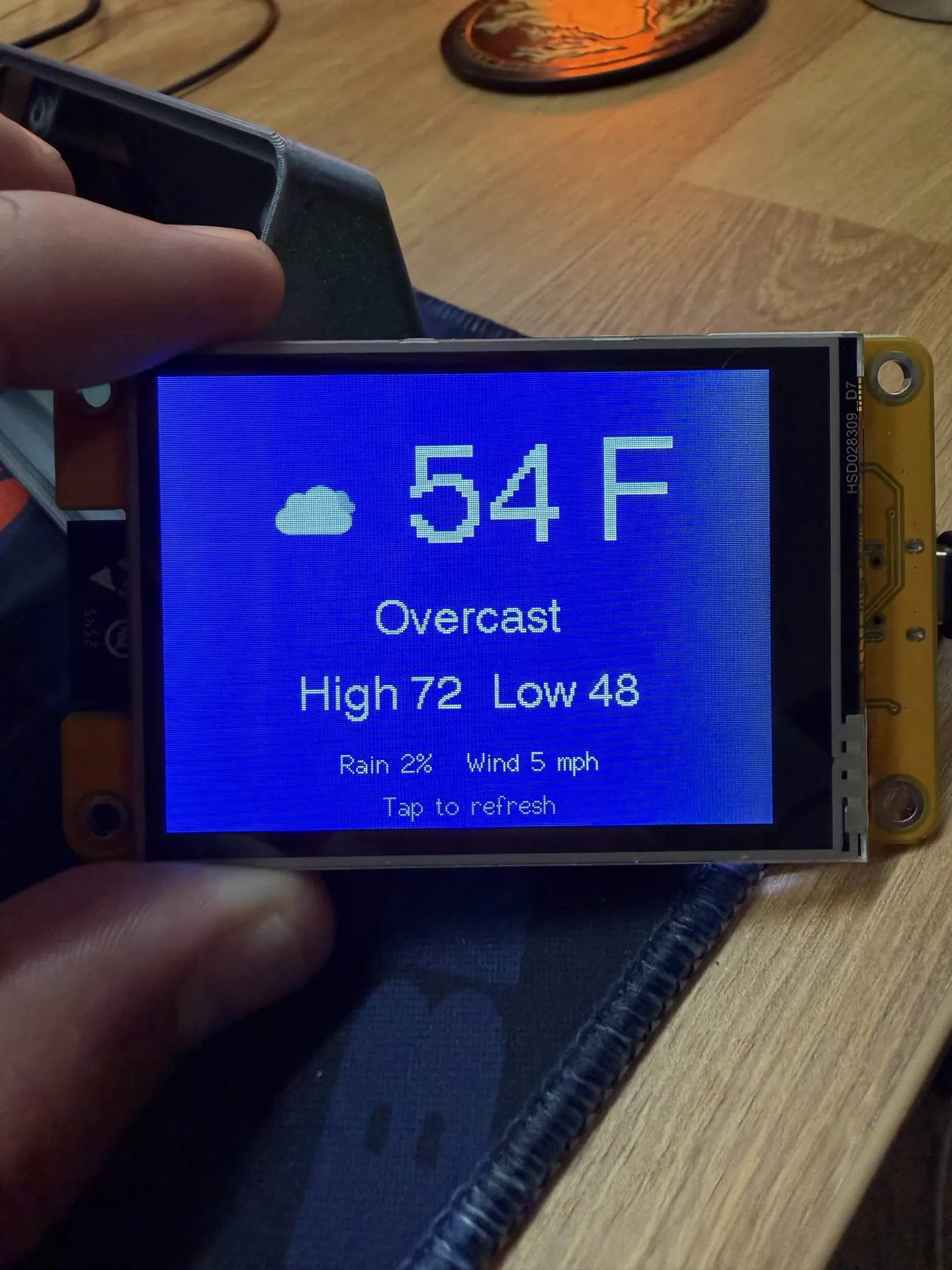
The “what to wear” part is the bit I like. Open-Meteo gives hourly “feels like” temperature and rain chance, so I pick three moments (8 am, noon and 3 pm) and compare them. The rules live in one place, as named constants:
function outfit(feelsF: number): string {
  if (feelsF < HEAVY_COAT_BELOW_F) return 'heavy coat';
  if (feelsF < COAT_BELOW_F) return 'coat';
  if (feelsF < JACKET_BELOW_F) return 'light jacket';
  if (feelsF < LIGHT_CLOTHES_FROM_F) return 'T-shirt';
  return 'light clothes';
}
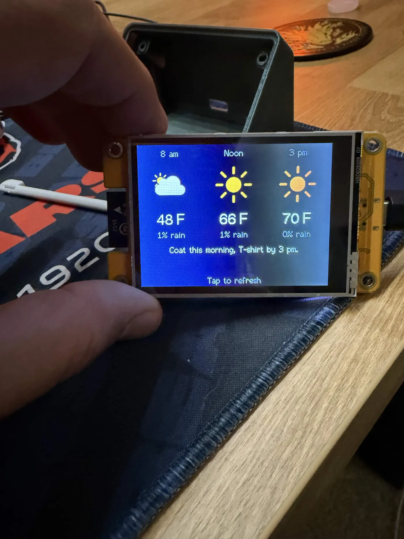
The cutoffs are 32, 50, 65 and 85 °F, and an umbrella gets mentioned at a 40% rain chance. The server code is tested, and it produced the line you can see on the board:
One honest wart: the firmware carries its own copy of those rules, because the board talks to Open-Meteo directly. The C++ is marked with a comment saying it mirrors the server’s TypeScript, and the duplication goes away once the board reads the advice from the server.
Icons without an SVG renderer
I wanted proper weather pictures, and Meteocons (MIT) are lovely. The repo has moved to basmilius/meteocons, and the finished SVGs now ship as an npm package, @meteocons/svg-static. I downloaded the tarball into a scratch folder and copied ten icons into the project, along with the license file.
Then I hit the next problem: the board wants raw RGB565 pixels, and I had no way to turn an SVG into those. After sudo apt install librsvg2-bin (a system tool, not a project dependency), I wrote a small Node script that uses only built-ins. It runs rsvg-convert, decodes the PNG with zlib, blends each pixel onto the screen’s background color, and writes the result into a generated icons.h:
const blend = (c: number, a: number, bg: number) => Math.round((c * a + bg * (255 - a)) / 255);
const rgb565 = (r: number, g: number, b: number) =>
  ((r & 0xf8) << 8) | ((g & 0xfc) << 3) | (b >> 3);
Blending against the real background gives smooth edges, but it comes with a trap, which I’ll get to in a moment. The icons also needed tft.setSwapBytes(true), because the panel wants the high byte first. The background color mattered too: my first “navy” photographed as a very bright blue, so I switched to a darker slate (RGB 16, 24, 40), which makes the icon colors stand out. Flash use is now 83% of the default app partition, so a future audio decoder will need a bigger partition layout.
A header and a home screen
The next idea was a permanent header: a greeting (“Good morning” with a name), a clock, and a row of buttons, with a grid of function tiles below. The greeting and clock come from NTP (configTzTime with a POSIX timezone string), which only asks a time server for the time. I split the weather code into its own files, regenerated the icons at a smaller 48 px size so everything fits under a 72 px header, and wrote the tile list as an array, so adding a function to the Home grid is one line.
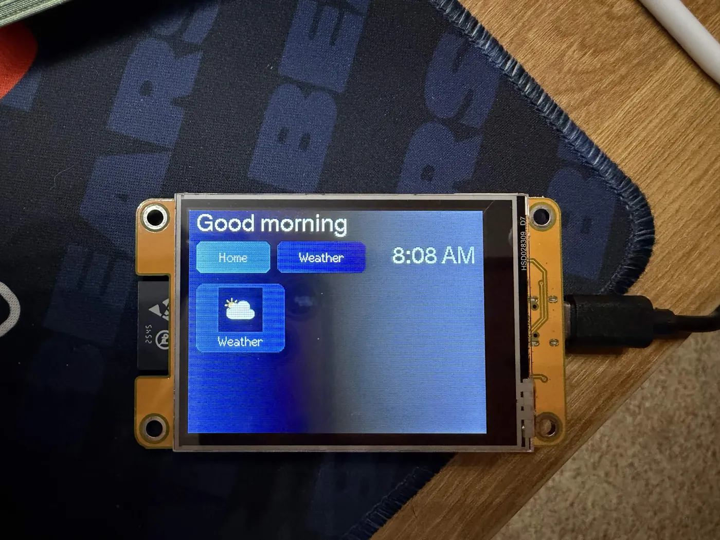
Look closely at that tile and you’ll see the trap. The icon has a dark square around it. I blended the icons onto the dark background, then filled the tile with a lighter button color, so the mismatch shows as a box. The fix was to draw tiles as an outline on the same dark background instead of a fill, with a comment explaining why so I don’t “improve” it later.
What’s not done
- Speaker: the CYD has a built-in speaker port with its own amplifier, but it takes a small 1.25 mm JST plug. The speaker I already own has a different connector, so I need a different one. I haven’t tested any audio.
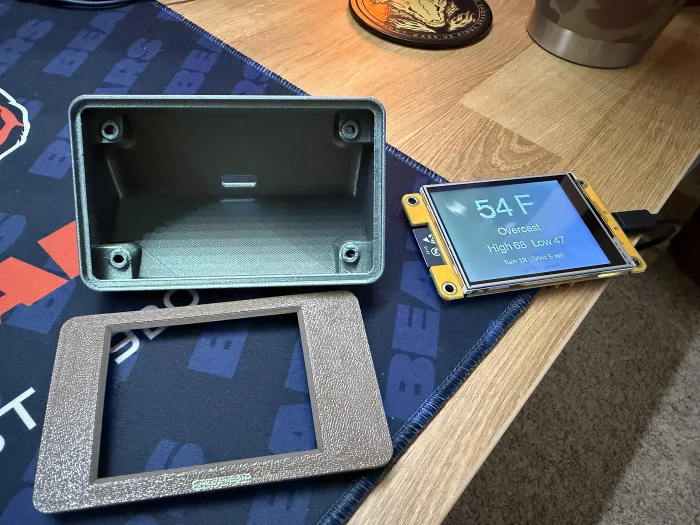
- Case: I printed the CYD Desk Buddy enclosure from MakerWorld, the green body and bronze bezel in the first photo. I haven’t fitted the board yet, and I expect to modify it for the microSD slot and the speaker.
- Dimming: a screen that’s fine on a desk is too bright in a bedroom, so night dimming and tap-to-wake are next on the list.
- The server link: the board still calls Open-Meteo directly. Reaching my server from WSL2 is the open question, and it unlocks everything personal on the display.
The thing I keep relearning with hardware is that the interesting failures are rarely in the code you wrote: a USB path I couldn’t see into, and one pinned library commit that lacked an API I assumed it had.